
A home plumbing riser diagram is a crucial schematic that shows how water supply lines, waste, and vent pipes connect vertically through a building. It helps visualize the flow of water from the main supply to fixtures and the drainage system. Drawing a riser diagram involves accurately tracing these pipes and fixtures, marking valves and pipe sizes, ensuring proper water pressure and venting for the plumbing system’s efficiency and code compliance. This step-by-step guide will take you through the essential process of creating a clear and functional home plumbing riser diagram to aid in construction, renovation, or permitting purposes.
Understanding Plumbing Riser Diagrams’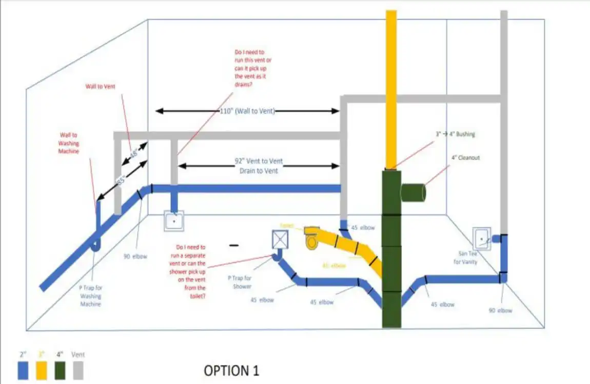
What Makes Riser Diagrams Special?
A plumbing riser diagram serves a unique purpose in the world of construction drawings. Unlike other types of plumbing drawings, it focuses specifically on the vertical relationships between pipes and fixtures. This vertical perspective makes it incredibly useful for understanding how water and waste flow through multi-story buildings.
The primary purpose of these diagrams is to clearly illustrate to plumbers, contractors, and inspectors how pipes connect between floors. They reveal critical information, such as pipe sizes, flow directions, and connection points, that may be hidden in other types of drawings.
How Riser Diagrams Differ from Other Plumbing Drawings
Many people confuse riser diagrams with other plumbing drawings, but each serves a distinct purpose:
Schematic diagrams show the overall plumbing system layout, eliminating the need to worry about exact locations or scale. They’re like subway maps – simplified for clarity.
Blueprints provide detailed floor plans with precise measurements and locations. They show where pipes run horizontally through walls and floors.
Riser diagrams bridge the gap between these two. They display vertical pipe runs in a clear and organized manner that’s easy to understand and follow.
Common Symbols and Notations
Learning the language of house plumbing diagrams is crucial for creating accurate drawings. Here are the most important symbols you’ll encounter:
- Solid lines represent water supply pipes
- Dashed lines indicate drain and waste pipes
- Circles with letters mark different fixtures (T for toilet, L for lavatory, S for sink)
- Arrows show flow direction
- Numbers indicate pipe sizes in inches
Benefits of Accurate Riser Diagrams
Creating a proper riser diagram offers numerous advantages. It helps prevent costly mistakes during construction or renovation. Contractors can quickly understand your plumbing layout without extensive explanations. Building inspectors appreciate clear documentation that shows code compliance. Most importantly, you’ll have a permanent record of your plumbing system for future reference.
Step-by-Step Process to Draw a Home Plumbing Riser Diagram
Gather Home Plumbing System Information
Your diagram is only as good as the information you collect. Start by creating a comprehensive inventory of your plumbing system. Walk through your home with a notebook and document every fixture, valve, and visible pipe.
Water supply points are your starting point. Locate your main water line entry, water heater, and any secondary supply lines. Note the size of these pipes – typically ¾ inch or 1 inch for main lines.
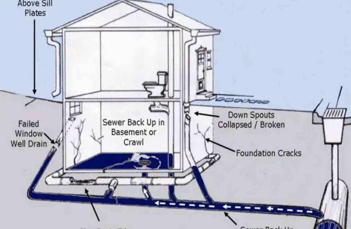
Drainage points require careful attention. Locate the point where each fixture drains and trace the path to your main sewer line. Don’t forget about floor drains in basements or utility rooms.
Vent systems are often overlooked but critically important. Look for pipes extending through your roof – these are plumbing vents that prevent sewer gases from entering your home.
Understand Plumbing Code Requirements
Before putting pencil to paper, familiarize yourself with local plumbing codes. These regulations ensure your plumbing system is safe and functional. While codes vary by location, some universal principles apply.
Pipe sizing requirements dictate minimum diameters for different fixtures. For example, toilets typically require 3-inch drain lines, whereas bathroom sinks need only 1¼-inch lines.
Sketch a Rough Layout
Begin with a simple sketch that shows your home’s basic structure. Draw vertical lines representing each house floor, from basement to roof. Mark the approximate locations of bathrooms, kitchens, and utility areas.
This initial sketch doesn’t need to be perfect. Think of it as a framework that you’ll refine later. Use light pencil strokes so you can easily make changes.
Label each floor clearly and indicate ceiling heights. This information helps when calculating house pipe runs and ensuring proper drainage slopes.
Identify Water Supply, Drainage, and Vent Systems
Now comes the detailed work of mapping your three main plumbing systems. Each system requires a different treatment in your diagram.
Drainage systems flow in the opposite direction. Start at each fixture and trace the path to your main sewer line. Remember that drain house pipes increase in size as they collect waste from multiple fixtures.
Use Standard Symbols and Labeling
Professional diagrams rely on standardized symbols that are universally understood within the industry. Using these symbols makes your plumbing diagram more useful and experienced.
Fixture symbols should be clear and consistent. A toilet might be represented by a circle with “WC” (water closet) inside. A sink could be shown as a rectangle with “LAV” for lavatory.
Pipe type indicators help distinguish between different materials. Copper pipes may be identified by one pattern, while PVC pipes use a different one. Include a legend explaining your symbols.
Size notations are crucial for accurate diagrams. Write pipe diameters directly on the lines, using standard measurements (½”, ¾”, 1″, etc.).
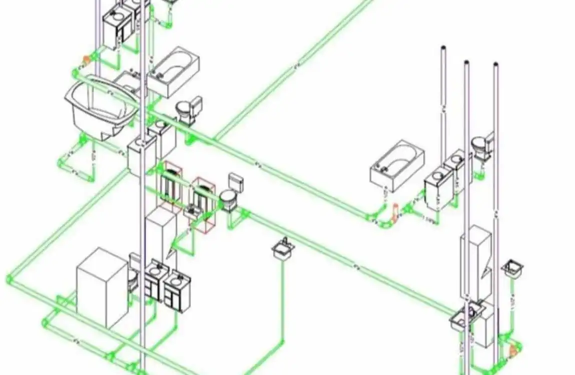
Draw Vertical Pipe Runs with Correct Alignments
This step transforms your rough sketch into a proper riser diagram. Focus on showing how house pipes travel vertically through your home.
Stack alignment is critical. Waste stacks should run straight down whenever possible. Any offsets or direction changes need careful documentation.
Branch connections show where horizontal pipes meet vertical stacks. Draw these at appropriate angles – typically 45 degrees for waste lines.
Support locations indicate where pipes attach to your home’s structure. This information helps during installation or repairs.
Indicate Pipe Sizes, Flow Directions, and Connections
Adding technical details brings your diagram to life. These specifications transform a simple drawing into a useful technical document.
Pipe sizes should be noted at every change in diameter. Use standard house plumbing sizes and specify whether the measurements are for internal or external diameter.
Test the logic of your house system. Trace each fixture’s water supply and drainage path. Everything should flow naturally without impossible connections.
Digitize Your Hand-Drawn Diagram
If you started with pencil and paper, consider creating a digital version of it. Digital house diagrams are easier to share, modify, and store.
Scanning options range from smartphone apps to professional scanners. Ensure your scan is high-resolution and clearly legible.
Tracing software can convert your sketch into clean digital lines. Programs like Inkscape offer free tools for this purpose.
Cloud storage protects your diagram from loss. Save copies in multiple locations for house future reference.